As part of the repair process for the Apple II Europlus, I have been testing each IC on the motherboard, to ensure it is working correctly. I have been able to test many of the 74 series ICs with my Xgemu 866 Universal Programmer, but there are some ICs that require more complex circuits to test than the Xgemu can provide.
There are a number of different test circuits that can be built to test a 6502, but for simplicity, I used the simple NOP design, where a 1MHz clock is applied, and the data lines are 'hard wired' to either 5v or ground to pass a singlecommand to the CPU - in effect telling the CPU to run the same command over and over. Because the NOP instruction causes no changes to the processor other than the normal incrementing of the program counter to the next instruction, this will cause the address lines to increment over and over - i.e. count from 0 to 65536 over and over.
So how to pass the NOP command?
I referred to the 6502 command reference here: http://www.obelisk.me.uk/6502/reference.html
The NOP instruction is Opcode EA, converting from hexidecimal to binary is 11101010.
This means that we need to wire data lines to 5v, 5v, 5v, GND, 5v, GND, 5v, GND. However, because the command works "in reverse" - i.e. the first 1 in the binary sequence above actually corresponds to data bit 7, the next to data bit 6, the actual wiring from D0 to D7 is:
D0 = GND
D1 = 5v
D2 = GND
D3 = 5v
D4 = GND
D5 = 5v
D6 = 5v
D7 = 5v
Aside from the data bus lines, we also need to provide power to the CPU, as well as a ground (there are 2 GND pins on the 6502) We also need to tie some other lines to 5v, as they are active low on the CPU. These lines are RDY, IRQ, NMI and RST.
Before the CPU starts executing instructions, it needs to be reset. I added a small pushbutton to pull the reset line to GND so I can easily reset the CPU. This is wired also to 5v, via a 1K resistor.
One other small "gotcha" - the 6502 executes instructions pretty rapidly - i.e. it will probably be executing the NOP instruction about 250,000 times a second. This means seeing the output of the NOP commands on the address lines impractical on the lower bits - A0 will be on and off 250k times a second, A1, 125k, A2 62.5k etc etc. So, in my testing circuit, I use the higher address lines A15, A14, A13 - as these are "oscillating" at roughly 8Hz, 16Hz, 32Hz respectively.
Here are the 6502 Pinouts:

Here it is all laid out on the breadboard:
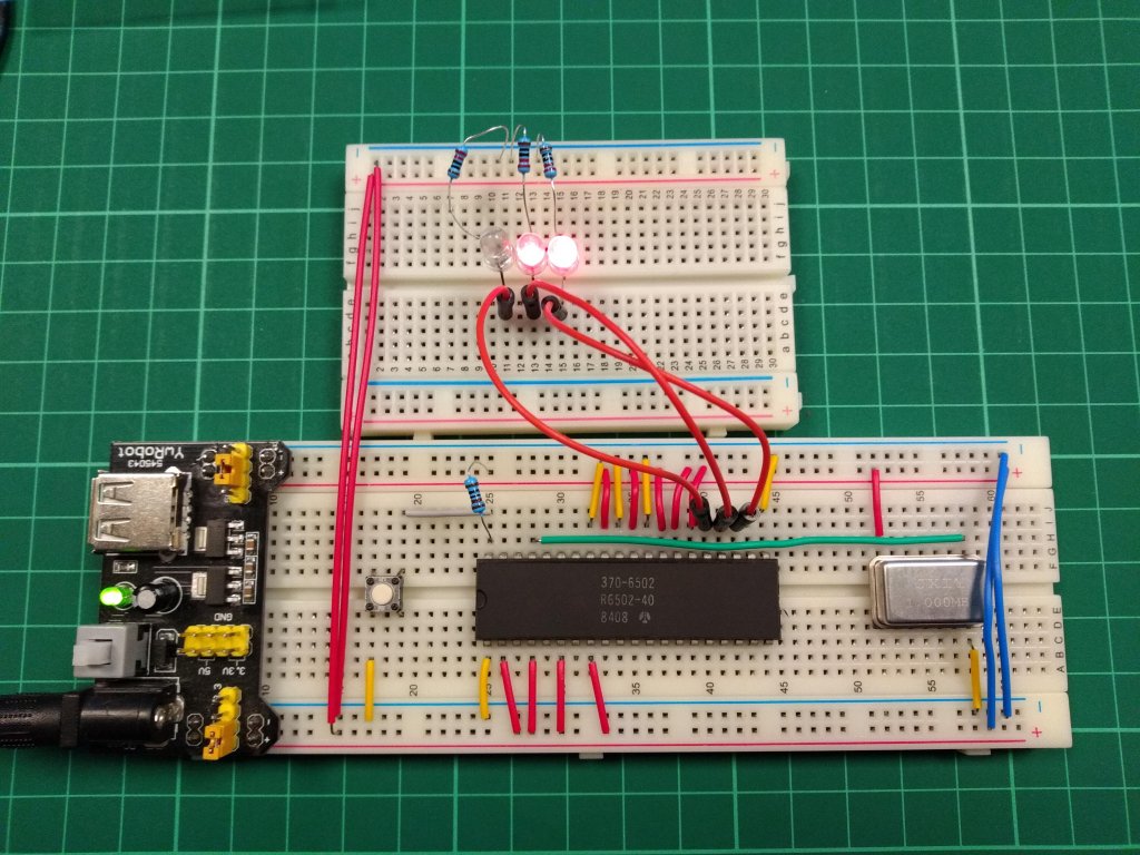
Wiring it all up and pressing reset gets us some lovely blinking lights - great! This CPU seems to be working OK.
Here are some waveforms:
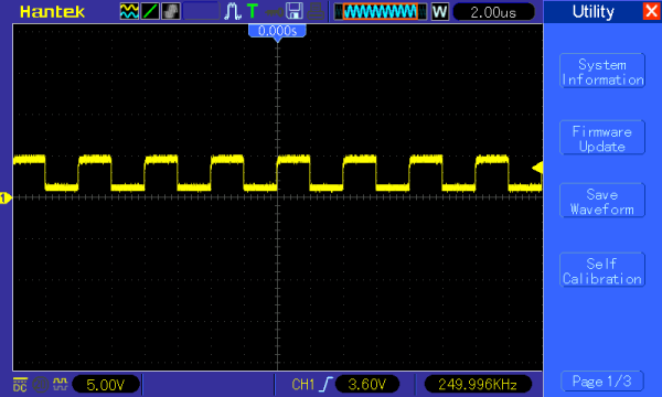
1MHz Input

Output from A0 - note 250KHz
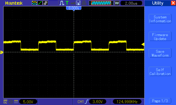
Output from A1
Output from A14

Output from A15 - 8Hz

What does a broken CPU look like? Well, it varies from CPU to CPU - some will not power on at all - i.e. you will see no output on the address lines.
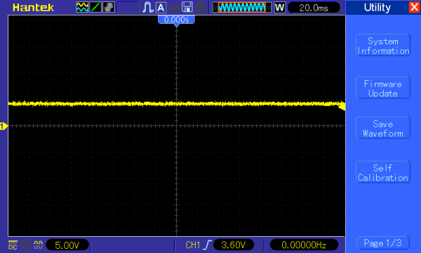
In my case, the 6502 from the Europlus puts the LEDs on all the time:

Also, testing with an oscilloscope just shows 5v on all of the address lines - all of the time.
Sadly, I think this 6502 - a Synertek with datecode 81/35 is broken, and will have to be replaced.