My girlfriend has for many years been a keen baker of all things sweet and savoury. Working exclusively with sourdough, it has been sometimes difficult to ensure that exact temperatures are maintained through the fermentation and proofing stages. After a few disappointments where the dough failed to rise (usually because it got cold in the kitchen overnight!) I realised it should be quite simple to build a temperature controlled bread proofing box.
Note that this is a little region specific, UK for me - as is any project that uses mains electricity, simply because of the differing plug/socket/wiring standards. However, with small adaptations, the basic idea is the same.
All in all, this was a fun project to try. It took an hour or two to build and test, and cost £60 in materials.
Materials Required
- 1x Temperature controller - I used a commonly available Inkbird ITC-1000 - Link
- 1x Large insulated box - I purchased a 35L polystyrene "fish box" from a packing supplier - Link
- Mains Plug - I used a standard 13A fused type, with the fuse swapped to a 6A - Link
- 5M 2 core electrical wire - I used 0.75mm flexible wire, rated for 6 Amps - Link
- Bulb/Heat source - I used an old E27 50W incandescent lamp I had lying around - Link
- Bulb holder/Socket - To match the bulb type you are using (bayonet/screw) - Link
- Cable gland - To match the wire size (approx 6.5mm) I used a PG9 gland (from 4mm to 8mm wire diameter) - Link
Test Wiring
I tend to test-wire a project such as this, to ensure that everything is functional and working before I mount the components and wiring in its final enclosure.
It goes without saying, that all of this cabling is completed without anything connected to the mains electricity, and you should be extremely careful - mains voltage should be respected and feared.
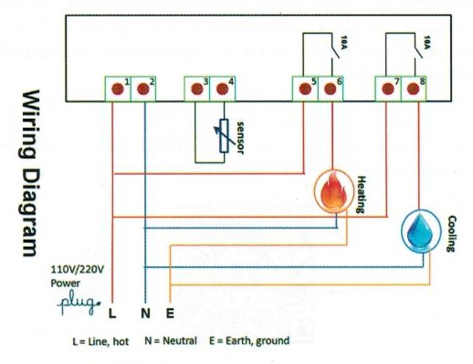
The ITC-1000 controller itself is very simple - here is a wiring diagram supplied with the unit:

As you can see from this, it has a number of terminals:
- Mains input (1/2)
- Temperature Sensor (3/4)
- Heating relay (5/6)
- Cooling relay (7/8)
In this iteration of the project, I only used the heating relay, so terminals 7 and 8 can be ignored.
Firstly, a length of the electrical wire (approx 3m) needs to be appropriately wired with a plug. The live and neutral wires are then connected to the first set of terminals. Live to 1, Neutral to 2.
Secondly, a bridge wire needs to be connected between the live terminal of the temperature controller on terminal 1, and the first terminal of the heating relay on terminal 5. This is because the relay is not connected internally to the live/neutral input - it is simply a switch. I cut a small length of the 2 core wire, and used one of the cores as the bridge wire between terminals 1 and 5.
Thirdly, a length of the two core wire needs to be connected to the bulb holder/socket. The live connection is connected to terminal 6, and the neutral connection is connected to terminal 2. The 50w bulb was then fitted into the holder.
Finally, the temperature sensor needs to be connected to terminals 3 and 4 - it can be plugged in either way.
Once all of the connections were double-checked, I powered on the unit and ensured that it worked correctly. No loud bangs - good! On to testing the on/off functionality of the temperature controller.
Temperature controller programming
On the ITC-1000, there is a button marked S, which when held down for a couple of seconds gives access to the menu.
The only menu items I needed were TS and DS:
- TS = Temperature set - At what temperature should the heater circuit turn off?
- DS = Difference Set - How far below TS should the temperature fall before the heater circuit is turned on?
Knowing that the optimum temperature for proofing bread is 24 degrees, I set TS to 24. I set DS to 0.5, so that if the temperature dropped to 23.5, the heater circuit would come on.
Once the options are set, pressing the power button once saved and activated the settings.
Testing "outside the box"
With the temperature set appropriately, the lamp lit up, as the temperature in the room was around 20 degrees.
I held the temperature sensor in my hand to warm it up, and once the temperature reached 24 degrees, the lamp turned off. I put down the sensor, allowed it to cool, lamp came on. I repeated this a few times to ensure that all was working as expected.
Fitting the wiring inside the box
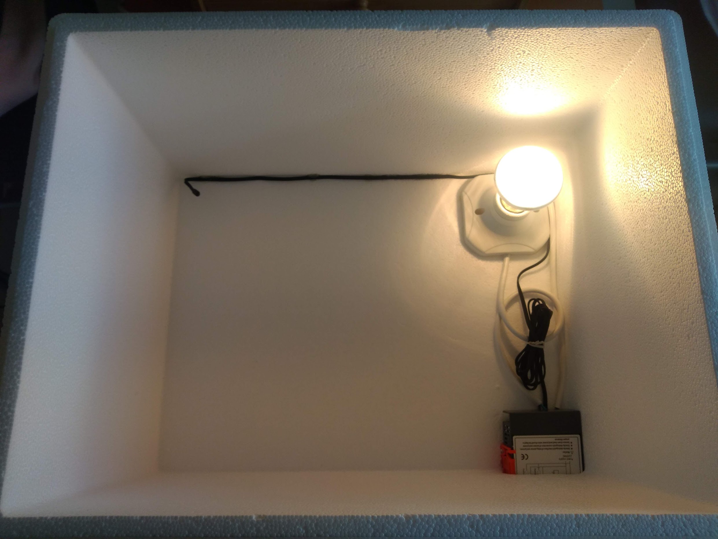
Because I chose a polystyrene box, it was relatively simple to cut a small hole in the rear for the electrical cable. I used a cable gland to pass the cable and secure it neatly, although the thickness of the box (20mm) meant that I needed to cut away at the material to allow the gland to be tightened up.
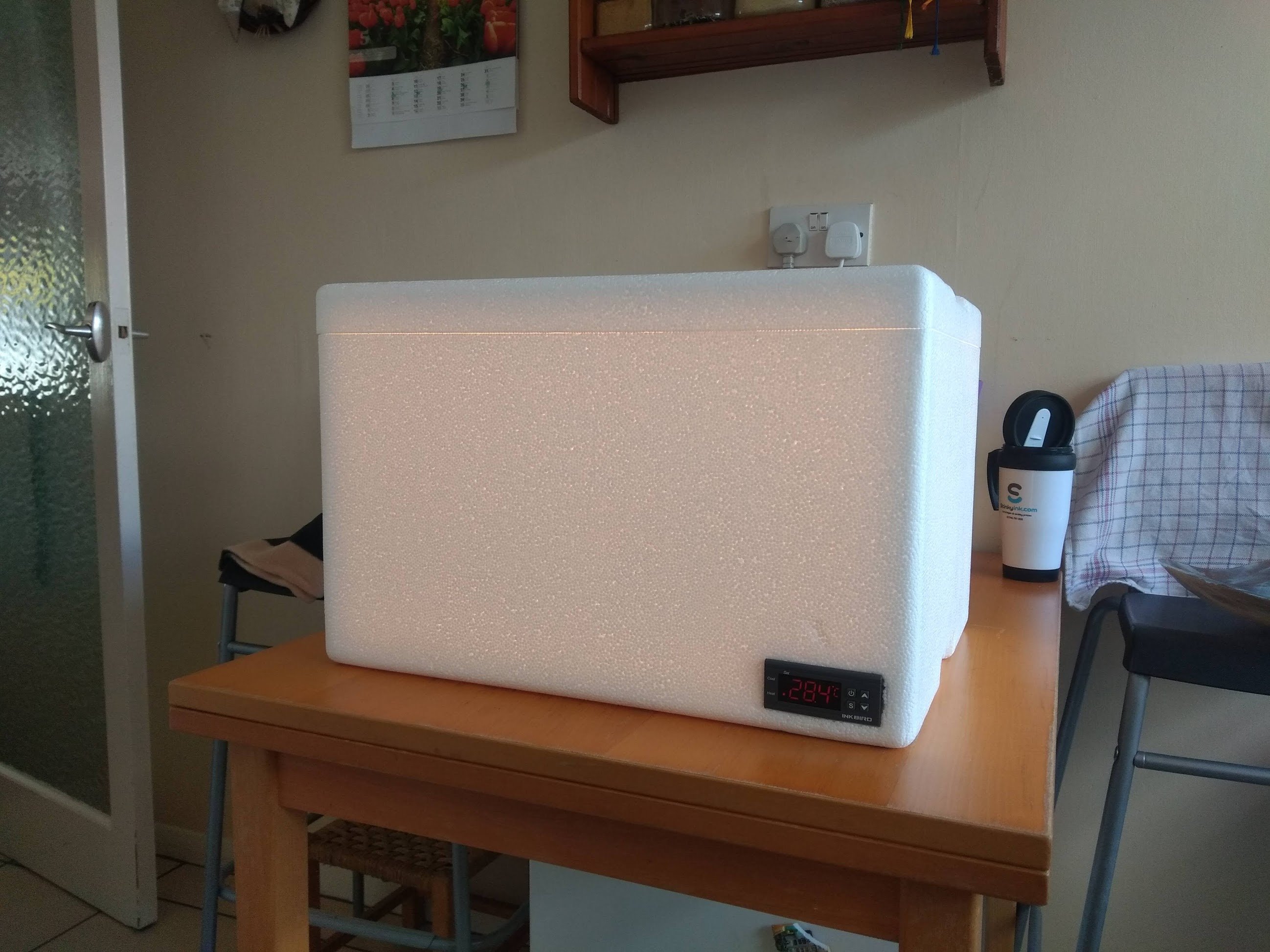
I then cut a slot in the front of the box to allow the temperature controller to be slotted in. Again, this was very simple - draw a template around the controller, and use a flat bladed screwdriver to cut away at the material.
To actually fit the wiring and controller inside, I had to disconnect the mains cable from terminal 1 and 2, and then reconnect with the mains cables passed through the gland. Otherwise, the cables for the temperature sensor and lamp remained connected.
I then used a glue gun to secure the temperature sensor cable to the edge of the polystyrene box, and the lamp holder base to the base of the box.

Testing the box
Once all the cables had been re-routed in the box, I then tested that the whole device worked as expected - it did, and in fact it heated up very quickly (less than 1m) from 20 degrees to 24 degrees. I allowed the cycle to run a few times to ensure all was well, and then used hot glue to route the temperature probe to an appropriate location away from the heat source.
The project was then complete - I have a happier girlfriend, and more tasty bread to enjoy in future!

How big is a 35L box?
- Internal dimensions: 420mm (16.5") x 320mm (12.6") x 250mm (9.8") with 33.6 litre (59.13 pints) capacity.
- External Dimensions: 468mm (18.4") x 368mm (14.5") x 300mm (11.8")
Improvements I would like to make
- Larger box - a 35L box is not quite large enough to proof multiple loaves, or some larger breads like Brioche.
- Move the control unit external to the box - This could save valuable space inside the proofing box itself, and better tolerate moister conditions.
- External junction box for wiring - although the jump wire between terminals 1 and 5 works, I do not like long term having multiple wires secures in the small terminals of the temperature controller. An external junction box would be a little neater.
- Cooling fan/Peltier - this project is great when the weather is cold, but in the summer, using a cooling fan or peliter may be required to keep the inside of the box cooler than the surrounding air.
- Timer/countdown feature - for convenience more than anything - if you know you need to proof the bread for say, 3 hours, it would be good for the unit to turn itself off automatically.